PCIe has long stopped being a characteristic that can be judged by the simple rule of “the newer the generation, the better.” In a modern server platform, it is no longer just an expansion bus but one of the elements of the overall I/O architecture. In practice, final performance is determined not only by 16 GT/s in PCIe 4.0 and 32 GT/s in PCIe 5.0, but also by how many lanes are actually available to the device, how the board topology is designed, which socket the slot is tied to, whether traffic passes through the chipset, whether cooling is sufficient, and whether the entire system is limited by the controller, memory, or software stack. PCI-SIG explicitly states that PCIe 4.0 provides 16.0 Gbit/s per lane in one direction and PCIe 5.0 provides 32.0 Gbit/s, meaning the fifth generation really does double raw bandwidth compared to the fourth. But that does not mean an application, a server, or a specific device will become twice as fast.
That is exactly why the topic of PCIe Gen4 and Gen5 is especially important now. Modern servers simultaneously carry fast NVMe storage, 100/200/400GbE network adapters, GPUs and accelerators, as well as dense I/O configurations in virtualization, SDS, and AI/HPC. In such an environment, PCIe becomes not a background detail but a limiting factor: a mistake in slot choice, link width, or topology can matter more than the mere presence of Gen5 on the box. This is especially noticeable in systems where the goal is not just to achieve peak throughput but to maintain stable latency and predictable behavior under load.
What PCIe bandwidth means in practice
PCIe is structured as a set of serial lanes. Each lane transfers data independently, and total bandwidth is determined by the interface generation and the number of lanes: x1, x4, x8, x16. That is why comparing only Gen4 and Gen5 is incorrect. PCIe 5.0 x4 and PCIe 4.0 x8 are close in terms of available bandwidth class, while PCIe 5.0 x8 is already comparable in “channel capacity” to PCIe 4.0 x16. This logic is what matters in server architecture: you have to calculate not an abstract generation but the combination of “version × width × actual wiring scheme.” Intel also emphasizes in its explanatory materials that each PCIe generation doubles throughput compared to the previous one, but the practical value depends on how exactly the platform uses those lanes.
Another source of confusion is the difference between signaling rate and usable application bandwidth. GT/s is a signaling speed, not ready-made gigabytes per second that an application is guaranteed to receive. In addition, PCIe is a full-duplex interface: it can transfer data simultaneously in both directions. This matters for network adapters, accelerators, and some storage scenarios, but in real workloads it is rare for both directions to be loaded equally and continuously. That is why, when evaluating performance, it is always useful to clarify whether we are talking about a one-way stream, total bidirectional channel capacity, or a peak value from the specification.
You also need to remember negotiation to the lowest common denominator. A Gen5 device in a Gen4 slot will run as Gen4. An x8 device in an x16 slot will not suddenly become x16. Moreover, a physical x16 slot may be electrically wired as x8 and may sometimes share lanes with another slot, an M.2 connector, or a backplane node. This is one of the reasons why the formal slot list on a board almost never provides a full understanding of performance without a lane map and a platform manual. In the server world, this is especially critical because that is where you often have to balance NICs, NVMe, GPUs, DPUs, and RAID/HBAs within a finite number of CPU lanes.
Most popular


PCIe Gen4 and Gen5: the basic numbers

Below is a practical table that helps quickly correlate generation, width, and typical usage scenarios. Usable bandwidth values are approximate and intentionally avoid low-level encoding details: for engineering estimation, that is enough.
| Configuration | Raw rate per lane | Approximate usable one-way bandwidth | Approximate total bidirectional bandwidth | Typical devices |
|---|---|---|---|---|
| PCIe 4.0 x4 | 16 GT/s | ~7.9 GB/s | ~15.8 GB/s | NVMe SSD |
| PCIe 4.0 x8 | 16 GT/s | ~15.8 GB/s | ~31.5 GB/s | NICs, accelerators, controllers |
| PCIe 4.0 x16 | 16 GT/s | ~31.5 GB/s | ~63 GB/s | GPUs, high-speed NICs |
| PCIe 5.0 x4 | 32 GT/s | ~15.8 GB/s | ~31.5 GB/s | Gen5 NVMe SSD |
| PCIe 5.0 x8 | 32 GT/s | ~31.5 GB/s | ~63 GB/s | NICs, DPUs, accelerators |
| PCIe 5.0 x16 | 32 GT/s | ~63 GB/s | ~126 GB/s | GPUs, AI/HPC accelerators |
PCI-SIG defines PCIe 4.0 as 16.0 Gbit/s per lane in one direction and PCIe 5.0 as 32.0 Gbit/s. This is what produces the doubling of channel capacity between generations. On the application level, this table leads to two practical conclusions. First: for an ordinary single NVMe drive, the critical factor is specifically the x4 link, and moving from Gen4 x4 to Gen5 x4 really does raise the interface ceiling by about two times. Second: for NICs, GPUs, and accelerators, the question often depends not only on generation but also on the need for x8 or x16 connectivity without width degradation.
Why theoretical bandwidth is almost never equal to real bandwidth
PCIe has an unpleasant feature for anyone who likes neat headline numbers: even if the link comes up in the required mode, that still does not mean the application will see comparable speed. First, there is protocol overhead. Second, there is workload behavior. A sequential stream with large blocks can come close to interface limits, while small-block random I/O may run into the controller, queueing, CPU, or memory long before bus bandwidth is exhausted. This is especially noticeable in storage: the same SSD shows a completely different picture in sequential read, write, mixed profile, and latency-sensitive workloads. In its NVMe and PCIe materials, PCI-SIG directly ties the practical value of the interface not only to bandwidth but also to latency, lane scalability, and overall platform efficiency.
In many cases, the bottleneck is located above or below PCIe. Above it are the CPU, NUMA, memory, file system, virtualization stack, drivers, network stack, RAID/ZFS/Ceph layer. Below it are the device controller, flash memory, internal queues, thermal throttling, PHY behavior, and link stability. That is why a drive marketed as delivering “up to 14 GB/s” is not obliged to show those numbers in an application. Samsung specifies PCIe 5.0 for the enterprise PM1743 and positions it as an SSD for high-performance servers; the Gen5 SSD class really has approached the boundaries of an x4 interface, but the application-level result still depends on the platform and the workload.
Another factor is latency tails. In enterprise environments, maximum speed is almost never the only criterion. If p99 and p99.9 degrade sharply under mixed load, a system may subjectively feel “slow” even when average throughput looks respectable. This is especially important for storage nodes, databases, NVMe-oF targets, packet processing, and AI pipelines that are sensitive to jitter. That is why PCIe bandwidth should be treated as a necessary but far from sufficient condition for high performance. Without that mindset, it is very easy to confuse a beautiful synthetic benchmark with real platform efficiency. (PCI-SIG)
Where PCIe breaks down at the platform level

Insufficient CPU lanes
The first bottleneck is a simple shortage of CPU lanes. A modern platform may formally support Gen5, but the number of lanes is still finite. When a single server is expected to accommodate GPUs, several NVMe groups, a high-speed NIC, a DPU, and additional controllers at the same time, competition for lanes begins. That leads to configurations where some slots only work if other devices are absent, where x16 turns into x8/x8, and where adding another drive removes full width from a neighboring slot. The problem is not that PCIe is bad, but that I/O design is always constrained by the CPU lane budget and the platform’s wiring scheme.
Bifurcation in such systems can be both a solution and a compromise. On the one hand, it allows one wide lane group to be split into several independent channels, for example x16 into 4×x4 for NVMe. On the other hand, it does not increase the total number of lanes and does not remove the need to distribute devices correctly across sockets and controllers. If a platform was designed for one x16 card and is then forcibly split for several drives plus another NIC, the risk of unexpected degradation rises sharply.
Chipset lanes versus direct CPU lanes
The second major limitation is the difference between direct CPU lanes and lanes hanging off the chipset. For the end user, both options may look like “the device is connected over PCIe,” but architecturally they are not the same thing. A device on CPU lanes gets a more direct path, while a device behind the chipset shares the uplink with other peripherals. As long as the device is a low-demand controller, a boot SSD, or moderate peripheral equipment, this may be acceptable. But if you place an intensive NVMe drive, a fast NIC, or a latency-sensitive device there, the bottleneck may appear much earlier than expected.
In practice, devices that are sensitive to bandwidth and latency are better planned on CPU lanes. The chipset is suitable for peripherals that do not constantly saturate the channel. This mistake is especially painful because formally everything may look correct: the link trains, the device works, the drivers do not complain, but performance is below expectations and unstable under mixed load.
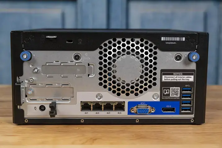
Physical width and electrical width are not the same
One of the most common mistakes is believing that a physical x16 slot necessarily provides electrical x16. On server and even workstation boards, that is far from always true. A slot may be x16 in form factor but x8 in electrical wiring. There are also layouts where width depends on whether neighboring slots are populated. Similar logic applies to M.2, U.2, U.3, and EDSFF: connection options that look identical may have fundamentally different real bandwidth and different lane origin.
That is why, in engineering work, it is not enough to look at a board photo or a short store specification. You need a lane map, a block diagram, a platform guide, and an understanding of which resources are shared between specific connectors. The marketing phrase “there is an x16 slot” without clarifying lane origin and distribution is useful only until the first real test.
Switches, retimers, and redrivers
The transition to Gen5 imposes much stricter signal-integrity requirements. In its materials, PCI-SIG specifically highlights 32 GT/s as a mode that requires tighter validation and compliance. In practice, that means long traces, dense layouts, complex backplane scenarios, and a large number of devices become noticeably more sensitive to channel quality. As a result, the role of retimers, redrivers, and PCIe switches grows.
For the user, this has several consequences. First, a Gen5 platform is almost inevitably more complex and more expensive to implement. Second, additional elements in the channel are not just a scaling convenience but also extra requirements for compatibility, power, cooling, and firmware. Third, link instability at high speeds may appear not as an obvious error but as suboptimal performance, speed fallback, unstable behavior under load, and difficulty reproducing results.
NUMA and device placement

In dual-socket systems, the question “which slot should I put the device into?” is often more important than the Gen4 versus Gen5 debate. If a NIC, NVMe group, or accelerator is physically tied to one socket while the main compute workload and memory reside on the other, traffic starts crossing the inter-socket link. In that case, the real damage from poor NUMA locality can be greater than the gain from moving to a newer PCIe generation.
That is why, for heavily loaded servers, it is important to consider affinity, pinning, thread placement, memory locality, and whether the slot matches the intended socket. Quite often, correct device and workload placement produces a bigger benefit than upgrading from Gen4 to Gen5 without changing topology.
Bottlenecks by device type
NVMe SSD
SSDs were the first to show that Gen5 can do more than merely exist on paper and can genuinely change the performance class of an x4 interface. Enterprise Gen5 SSDs already operate close to the limit of such a link: Samsung PM1743 is officially part of the PCIe 5.0 family and is positioned as a high-performance enterprise SSD. That means the interface question is no longer theoretical for fast drives. Gen4 x4 really can become the ceiling in sequential scenarios, while Gen5 x4 opens room for further growth.
But SSDs are also where it is especially important not to fall into linear thinking. If the workload is small-block, latency-sensitive, limited by CPU, file system, RAID/ZFS/Ceph, controller, or thermal throttling, the gain from Gen5 will be far smaller than expected. Moreover, Gen5 SSDs are typically hotter and more demanding in terms of cooling. That is why, for a single boot or application drive or for moderate enterprise workloads, Gen4 often remains a rational choice, while dense arrays of fast NVMe drives, large-data streaming, AI scratch space, and heavy storage scenarios are where Gen5 starts to show its value.
Network adapters
For NICs, evaluation should begin not with port speed but with actual traffic behavior. 25/50/100GbE often works well on Gen4, especially if the workload is not extreme in packet rate and the platform is designed properly. But as infrastructure moves toward 200/400GbE, SmartNICs, and DPUs, the host interface question becomes much more acute. Intel explicitly specifies PCIe 4.0, 16 GT/s, and x16 lanes for the E810-XXVDA4, which already shows clearly that even the 25GbE class at high port density requires a serious host-side channel if the goal is not merely to “bring the link up” but to stably serve heavily loaded cloud and communications scenarios.
At the upper end of the scale, this becomes even more obvious. NVIDIA positions ConnectX-7 as an adapter class of up to 400Gb/s, designed for modern cloud, AI, and enterprise workloads. At that level of network throughput, PCIe stops being a secondary issue: width, generation, NUMA, offload capabilities, DMA behavior, and how quickly the CPU can service the stream all matter. A platform may formally support the required adapter, but without the right topology, the server will not realize the full point of such a NIC.
GPUs and AI accelerators
With accelerators, the situation is more complicated than with SSDs or NICs. The mere presence of PCIe Gen5 x16 does not mean the bottleneck automatically disappears. AMD lists PCIe 5.0 x16 for the Instinct MI300X as the bus type, but alongside that it also highlights Infinity Fabric links, massive onboard memory, and the enormous internal bandwidth of its memory subsystem. This is a good example of how, in AI/HPC, accelerator performance is determined not only by the host link but also by memory architecture, inter-accelerator interconnects, and the pattern of data exchange between the CPU and the accelerator.
For inference, where the model or its working set is already placed on the accelerator, the role of the host link may be moderate. For training, data staging, multi-accelerator configurations, data streaming, GPUDirect-like scenarios, and close interaction with fast storage or networking, PCIe starts to matter much more. But even then, Gen5 is not a universal answer. Poor NUMA alignment, a shortage of lanes, resource contention between NIC and GPU, and inter-accelerator topology can consume the benefit faster than the bus version itself can provide it.
The most common mistakes when choosing PCIe

Below are the mistakes that most often lead to disappointment even in expensive configurations.
Looking only at generation and ignoring width. Gen5 x4 and Gen4 x8 are not the same thing, but neither are they worlds apart. Always evaluate generation together with lane count.
Assuming every physical x16 slot is electrically x16. Without checking the block diagram, this assumption is dangerous.
Ignoring CPU lane limits. The device may work, but a neighboring slot or drive group may lose width because of it.
Failing to distinguish CPU lanes from chipset lanes. For critical devices, this difference can completely change the final picture.
Forgetting about NUMA. The wrong slot can sometimes cut performance more severely than the difference between Gen4 and Gen5.
Expecting a linear doubling of application performance. What doubles is interface capacity, not necessarily application speed.
Evaluating SSDs only by sequential read speed. For most enterprise workloads, that is not enough.
Not accounting for Gen5 SSD and NIC cooling. Higher performance almost always brings higher thermal density.
Not checking lane sharing on the specific board. This is especially risky in systems with multiple M.2, OCP, U.2/U.3, and additional slots.
Ignoring the software stack. Quite often, the bottleneck is not in PCIe but in drivers, the hypervisor, the file system, or network processing.
How to tell whether the bottleneck is really in PCIe
Diagnosis should begin not with a hardware upgrade but with checking the facts. If a device is performing below expectations, the first thing to examine is negotiated speed and width. In practical operation, this often allows you to immediately rule out obvious issues: a card has linked as x8 instead of x16, a Gen5 SSD is running as Gen4 for some reason, or the device is installed somewhere other than intended. For modern GPU, NIC, and storage configurations, AMD directly recommends in its cluster documentation gathering PCIe device addresses in advance and checking that adapters and internal switches use the maximum available speed and width.
After that, topology must be verified. It is important to understand where the device sits — on CPU lanes or behind the chipset, which socket it is tied to, whether it shares lanes with another slot or port, and whether there are NUMA locality issues. Then thermals should be checked: a fast Gen5 SSD or NIC under insufficient cooling may throttle so heavily that it looks like “bad PCIe,” even though the real cause lies elsewhere.
The next step is to separate a PCIe bottleneck from CPU, memory, storage, and software stack limitations. If throughput is low while the CPU is busy, the problem may be in interrupt handling, queueing, the network stack, or application code. If throughput looks fine but p99 behavior is poor, the culprit may not be the interface but scheduling, contention, the file system, the RAID layer, or application-level GC and buffering. That is why synthetic and production-like tests must always be compared: the first shows hardware limits, the second shows how the system behaves under a real workload profile.
The practical checklist looks like this:
Check negotiated speed and negotiated width.
Determine whether the device is connected to CPU lanes or through the chipset.
Check NUMA locality relative to the CPU, memory, and workload.
Rule out thermal throttling.
Check lane sharing with slots, OCP, M.2, and drive backplanes.
Assess whether the workload is limited by drivers, the file system, the network stack, or the hypervisor.
Compare synthetic tests with the production workload profile.
Our most popular storage systems


When Gen4 is enough and when Gen5 is truly needed
The most expensive mistake is choosing Gen5 “just in case” without understanding whether it will actually matter for your workload. For typical virtualization, moderate enterprise workloads, most 25/50/100GbE scenarios, and single or non-extreme NVMe subsystems, Gen4 often remains an entirely rational choice. It is mature, predictable, usually easier in terms of heat and validation, and the gain from moving to Gen5 may remain visible only in pretty benchmark charts rather than in real production.
Gen5 is justified where there is a real need for higher I/O density per lane. That includes fast Gen5 NVMe arrays, 200/400GbE and modern SmartNIC/DPU deployments, accelerator-heavy AI/HPC servers, systems where it is important to reduce the number of occupied lanes and slots while maintaining per-device throughput, and platforms with a clear growth horizon. In other words, Gen5 is needed not because it is newer but because it removes a specific limitation in a specific architecture.
Below is an application-oriented summary for common scenarios.
| Scenario | What most often becomes the bottleneck | When Gen4 is enough | When Gen5 is needed |
|---|---|---|---|
| Single NVMe boot/app SSD | Controller, workload, file system, CPU | Almost always | Rarely, unless it is a very fast data drive |
| Array of fast NVMe drives | CPU lanes, cooling, PCIe switches, storage stack | If the array is moderate and does not reach the interface limit | When high density and maximum throughput per x4/x8 channel are required |
| 100GbE storage node | NUMA, CPU, DMA, storage stack | Often enough | With aggressive packet processing and high I/O density |
| 200/400GbE network appliance | Host interface, CPU, NUMA, offload | Already on the edge or insufficient | Often justified |
| GPU/AI server | Topology, inter-accelerator links, NUMA, host link | For some inference scenarios | For heavy accelerator-heavy configurations |
| General-purpose virtualization host | CPU, memory, storage stack, oversubscription | Usually enough | When the platform simultaneously carries very dense I/O |
Practical recommendations for designing a server or workstation
The correct order of actions is almost always the same. First, estimate the workload; then choose the PCIe generation. Not the other way around. If there is no understanding of the workload profile, block sizes, packet rate, the role of latency, and data-flow topology, any discussion of Gen4 versus Gen5 quickly turns into an argument about stickers on the box.
Next, the platform lane map needs to be checked. For critical devices, it is worth determining in advance which slots sit on CPU lanes, which ones share resources, which are tied to a specific socket, and how the layout changes when additional cards or drives are installed. NICs, fast NVMe groups, DPUs, and accelerators are best placed where the risk of unnecessary hops and uplink contention is minimal.
NUMA cannot be left until later. If a device works intensively with a specific memory pool or set of cores, its placement should match that. In dual-socket systems, otherwise it is very easy to build a server that looks ideal “on paper” but in reality constantly pushes data across the inter-socket link.
Bifurcation and expandability are better planned in advance. This is especially true for platforms where today you need one NIC and several SSDs, but tomorrow you may add two more drives, a DPU, or an accelerator. Reserve in topology and cooling matters more than imaginary savings at the start. For Gen5, this is especially relevant: higher speed usually also means greater sensitivity to heat, signal quality, and platform validation.
And finally, you need to think systemically. PCIe version cannot be analyzed separately from width, lane origin, NUMA, the software stack, and the workload type. “There is a Gen5 slot” and “the device really and stably runs as Gen5 xN under my workload” are two different statements. All of server engineering lies between them.
Conclusion
PCIe Gen5 is not a magic acceleration button and not an automatic recipe for every new system. It is the next level of bandwidth that is genuinely needed by some modern server configurations, but it only reveals its value in a properly designed platform. In many cases, the bottleneck is not in the PCIe generation itself but in the number of lanes, the electrical width of the slot, topology, NUMA, chipset uplink, cooling, firmware, and workload profile.
That is why the right question is not “should I choose Gen5?” but “which exact limitation in my system does Gen5 remove?” If there is no answer to that question, Gen4 often remains the more mature and rational choice. If there is an answer and it comes down to I/O density, fast NVMe, 200/400GbE, DPU, or an accelerator-heavy environment, then Gen5 stops being a buzzword and becomes an engineering-justified decision.
Sources: PCI-SIG, PCI-SIG FAQ, Intel, Samsung PM1743, Intel E810.
Content: