Resilience is not “buy a reliable server”. It’s about eliminating single points of failure (SPOFs) and proving—through testing—that the system survives typical incidents: losing one power feed, a fan failure, an array going degraded, a switch crash, a voltage sag, or a maintenance mistake. The difference between 99.9% and 99.99% is almost never “better hardware”; it’s power/cooling path design, operating discipline, monitoring, and regular drills. This article is a practical constructor: how to tie power + cooling + component redundancy into one coherent scheme—and how to verify it works in real life.
Terms and resilience levels
PSU (Power Supply Unit) — a computer/server power supply, i.e., a secondary power source inside the chassis.
PDU (power distribution unit) — a power distribution device used to deliver electrical power to equipment.
SPOF (Single Point of Failure): why it’s usually “not inside the server”
A SPOF is a component/node/path whose failure stops the entire service. In real incidents, the SPOF often lives above the server level:
- Power path: one PDU, one breaker group, one feed, one UPS.
- Cooling path: hot/cold air mixing, recirculation, clogged filters, poor layout.
- Network: one ToR switch, one switch PSU, one uplink.
- Management: BMC on the same network as production, unreachable during an outage.
Practical rule: “dual component” without a “dual path” often creates a false sense of safety.
Capacity redundancy: N, N+1, N+2, 2N—and what “paths” really mean
- N — exactly as much capacity/equipment as the load requires.
- N+1 — one extra element added to N (one UPS module, one fan, one chiller, etc.).
- N+2 — headroom for two failures / a failure plus a maintenance event.
- 2N — two fully independent sets, each able to carry the entire load (two independent power/cooling distribution paths).
Key nuance: component redundancy and distribution-path redundancy are different things. The Tier approach by Uptime Institute is about predictable infrastructure and distribution paths (power/cooling distribution paths), not just “one extra box” in a rack.
Levels: component → server → rack → room/DC → site/region → application
It helps to think in layers:
- Component (fan, drive, PSU, NIC).
- Server (dual PSUs, RAID, bonding, ECC).
- Rack (A/B feeds, two PDUs, two ToRs).
- Room/DC (UPS, generator, cooling, distribution).
- Site/region (DR site, geo-redundancy).
- Application level: sometimes a well-designed app/cluster lets you intentionally simplify node hardware (e.g., not chasing the most expensive 2N at a single rack if the service tolerates losing a node and recovers quickly).
HA vs DR—short and to the point
- HA (High Availability): survive local failures (component/node/rack) with minimal downtime (seconds–minutes).
- DR (Disaster Recovery): survive a site-level disaster (fire, long-term grid outage, DC unavailability) and restore on another site/region (minutes–hours).
Most popular refurbished servers


Power as the foundation of resilience

Redundancy inside the server: PSUs, feeds, load sharing
Two PSUs (often labeled 1+1) are only half the story.
What matters:
- Two PSUs ≠ two independent power feeds. If both are plugged into the same PDU / same breaker group, that’s one path—one SPOF.
- Most servers have two common modes:
- Balanced sharing: both PSUs share the load.
- Standby / cold-redundant: one PSU carries most of the load, the other stays in reserve (details vary by platform, but the logic is the same: if one fails, the other must handle the peak).
Typical field mistakes:
- Both PSUs are connected to the same PDU (or two “power strips” fed from one wall outlet).
- “A/B feed” exists on paper, but physically it’s the same upstream feed/panel.
- Power is sized “too tight”: when one PSU fails, the other overloads and the server reboots.
- Mixed cable/connector classes, poor contacts → localized heating → protective trips.
Practical wiring:
- PSU1 → PDU A, PSU2 → PDU B.
- PDU A and PDU B are fed from different breakers/feeds/UPS paths (within your maturity level).
- Physical labels on cables and PDUs so “hands errors” don’t turn into mass downtime.
Rack and room: PDUs, breakers, selectivity, phases
Without diving into electrical engineering, here’s the risk logic:
- Selectivity: during a fault, the “closest” breaker should trip, not an entire row/panel.
- Phase balance: phase imbalance = overheating/trips/unpredictable voltage sags.
- Peak regimes: consider not only average power, but peaks (boot storms, RAID rebuilds, fan ramps under rising temperature).
- Degraded operation when a feed fails: if you have A/B, calculate whether one feed can carry the entire load (that is the real “N logic” check).
Why “just a good PSU” won’t save you: power quality is not only “average voltage”, but also dips/transients/transfer times. That’s why, at the data-center level, distribution-path architecture and switching regimes matter—and are described in Tier/topology practices.
UPS and generator: what “uninterruptible” actually gives you
A UPS solves two different tasks:
- Cover micro-outages / grid dips and improve power quality.
- Carry the load while the generator starts (or until you perform a controlled shutdown).
UPS topologies:
- Line-interactive: better than “office” units, but not universal for critical loads.
- Online double conversion: typically provides the most predictable protection for IT loads (at the cost of price/losses). Terminology and classes appear in materials related to IEC 62040 and vendor glossaries.
About bypass:
- Bypass is needed for maintenance/emergency modes, but it can become a “hidden SPOF” if you don’t control its state and transfer conditions.
How to choose runtime:
- 5 minutes: bridge short outages and give ATS (automatic transfer switch) time to act.
- 10–15 minutes: a common choice “for generator start” (if the generator exists and is maintained).
- More is not always better: battery cost, maintenance requirements, and footprint grow—and batteries age anyway.
What you must test:
- Real battery capacity (not the “nameplate”).
- Transfer to battery and back.
- Maintenance scenarios: what happens if the UPS is on bypass, one module is in service, or a controller fails.
Also note that UPS batteries degrade over time, so testing real capacity should be performed regularly—or batteries should be replaced on schedule.
Cooling and thermal conditions: resilience “through temperature”

Why overheating is not only “a fan died”
Overheating today often shows up quietly:
- Higher density: local hot spots appear faster than room-level sensors react.
- Throttling: the service is “up”, but performance drops → response-time SLA dies.
- Coupling with power: higher temps increase fan speed and power draw, which stresses UPS/feeds—especially in degraded mode when you’re already “on one leg”.
Server cooling: N+1 fans, sensors, airflow
Inside the server, cooling redundancy is usually N+1 (the fan array survives one failure). But it works only if:
- Fan profiles are configured sensibly (no “quiet mode” where predictability is needed).
- You monitor inlet temperature, not only “CPU package”.
- Air actually flows through the chassis:
- no cable “curtains”;
- covers/air shrouds/blanking plates are installed;
- air channels are not blocked.
Rack checklist:
- Servers are oriented front-to-back.
- Cable management doesn’t block exhaust.
- Empty rack units are closed with blanking panels (otherwise recirculation eats your margin).
Rack/room level: hot/cold aisle, airflow management
The most common cause of “mysterious” overheating is air mixing:
- hot air returns to the inlet of nearby servers;
- cold air leaks into voids and never reaches equipment fronts.
Minimum sufficient practices:
- basic hot/cold aisle layout;
- blanking panels and sealing gaps;
- recirculation control (front sensors and, sometimes, a simple thermal walk-through).
Environmental ranges: temperature/humidity/dew point and rate of change
The goal is not “as cold as possible”, but stable—without condensation risk.
What you measure in practice:
- Dry-bulb: air temperature.
- RH: relative humidity.
- Dew point: critical for condensation risk.
- Rate of change: sharp swings are more dangerous than “slightly above average”.
Recommendations and environmental classes for IT equipment are published by ASHRAE TC 9.9 (including the reference card).
Top-selling network switches


Component redundancy: what to duplicate in a server vs at the system level
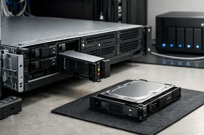
Drives and data: RAID vs replication vs backups
Separating these concepts is critical:
- RAID protects from a drive failure inside a node, but not from deletions, ransomware, logical errors, or many controller failures.
- Replication increases availability (HA), but it may also replicate bad writes or deletions.
- Backup—if done properly—is the only tool to “go back in time”.
Practical nuances:
- Hot-swap and spares reduce reaction time, but rebuild can heavily hit performance: the server “didn’t go down”, but your I/O SLA may already be broken.
- RAID works well for: OS disks, local services, small arrays where simplicity matters.
- For critical data, the system level often wins: replication/distributed storage + mandatory backups.
Network: two ports ≠ resilience
Common false constructions:
- “Two ports but one switch” — SPOF.
- “Two switches but both on one PDU/one power feed” — SPOF.
Working logic:
- Bonding/teaming/LACP is about aggregation and surviving a link/port failure, but it does not replace spreading across devices.
- For real resilience: different ToR switches/different paths/different PDUs for the network gear.
Memory and CPU: ECC, RAS, “silent errors”
ECC is not “for scientists”—it’s for predictability:
- virtualization, databases, file systems, caches—data integrity matters everywhere;
- “silent errors” in RAM can look like “random crashes” of applications.
RAS functions (platform-level) are part of the overall strategy: fewer unexplained failures and easier diagnosis.
Management access: BMC as part of availability
Resilience also means “management remains reachable during outages”:
- dedicated out-of-band management network;
- ACLs/isolation;
- monitoring BMC events (power, temperature, fans, sensors).
Monitoring and automation: without it, redundancy doesn’t work
What you must monitor
Minimum set of metrics:
- Power: PSU status, A/B input feeds, consumption (W/A), power events.
- Temperatures/cooling: inlet/outlet, CPU, VRM (if available), fan RPM.
- Disks/RAID: SMART/predictive indicators, array state, rebuild/degraded, controller errors.
- Network: link state, errors/packet loss, latency to key nodes.
- UPS: load, battery level, events, bypass mode.
Alerting and responses
Separate severity levels:
- Critical (immediate): power-feed failure, UPS on battery, inlet overheat, RAID degraded without hot spare.
- Important (within an hour): rising disk errors, a fan degraded, increasing drops on a link.
- Info: temperature/power trends.
Automated actions (only if tested):
- migration/evacuation in virtualization;
- graceful shutdown when UPS battery is near exhaustion;
- load shedding / increasing fan curves.
Rule: don’t automate what you haven’t tested.
Resilience testing: “trust, but verify”

A practical test set
Use this as a checklist and record results:
- Pull PSU: unplug one PSU on a running server. Verify: no reboot; the second PSU isn’t overloaded; alert fires.
- Power off PDU A (for part of a rack). Verify: everything critical stays on B; nothing is “accidentally” powered only from A.
- Cut upstream A feed (if your architecture allows safe testing). Verify A/B correctness at the distribution level, not only in the rack.
- UPS input event: transfer to battery and return. Verify correct events/alerts and stable load.
- Runtime test: controlled discharge to a safe threshold. Verify match to calculations and correct reactions (shutdown/migration).
- Generator test (if present): start, stabilize, transfer. Verify time, stability, and no “dip” during transition.
- Inlet rise test: simulate degraded airflow (e.g., safely change blanking/airflow conditions or increase load within limits). Verify inlet rise is visible and alerts trigger before throttling.
If your maturity is high, you can carefully apply Chaos Engineering: small controlled “breaks” in production under a runbook—but only after basic tests are safe and repeatable.
“Symptom → cause → action → verification”
| Symptom | Likely cause | What to do | How to verify |
|---|---|---|---|
| Server rebooted when one PSU was unplugged | both PSUs on one PDU / second PSU overload | separate A/B, re-calc power budget | Pull PSU test, load monitoring |
| When PDU A is switched off, part of the service “unexpectedly” drops | some gear is powered only from A | power audit, labeling, rewire | PDU A off test |
| UPS exists, but everything dies when grid power is lost | batteries degraded / UPS in bypass | battery tests, maintenance schedule | battery transfer + runtime check |
| Inlet rises while CPU is still “OK” | recirculation / no blanking panels / aisle mixing | blanking panels, sealing, layout | front sensors + thermal walk |
| Periodic “strange” lags without downtime | thermal throttling / RAID rebuild | alert on inlet/I/O, schedule rebuilds | load test + metric correlation |
| RAID is degraded without an alert | monitoring isn’t integrated with RAID | configure alerts/integration | force a test degraded state |
| Two ports exist, but the network disappears when a ToR fails | single switch/uplink is a SPOF | spread across two ToRs, verify uplinks | disable one ToR/uplink |
| Management is lost during a network incident | BMC on the production network | separate mgmt network, ACLs | disable prod network and check access |
| After generator transfer, some equipment drops | transients / incompatible modes | tuning, testing, align scenarios | controlled generator drill |
| In hot weather, disk/link errors increase | overall rack/room overheating | improve air management | temperature trends + airflow audit |
Runbooks: maintenance and postmortems
Without runbooks, redundancy degrades:
- UPS batteries age and lose capacity;
- filters clog and airflow worsens;
- fans wear out, noise/vibration grows;
- “near misses” are forgotten and repeated.
Keep an incident log and postmortems: what happened, why monitoring didn’t catch it earlier, and what you change in architecture/processes/maintenance schedules.
Balancing cost and availability: choosing the right redundancy level

A convenient selection logic:
- Dev/Test: downtime is acceptable → a solid server plus backups if needed.
- SMB web services: downtime costs money → dual PSUs, correct A/B, basic UPS, monitoring, RAID/replication as needed.
- Databases/VDI/critical services: downtime is expensive → 2–3 node cluster, spread across racks/ToRs, proven maintenance without downtime.
- When downtime is unacceptable: DR site/geo-redundancy, recovery testing, regular exercises.
Common non-obvious mistakes
- Two PSUs, but one PDU / one breaker group.
- “A/B feed” = two power strips in one wall outlet.
- Two switches, but both powered from one feed (or one UPS).
- UPS exists, but batteries have degraded—and nobody checks.
- UPS is always on bypass (or goes to bypass under load) and nobody alerts on it.
- Power is budgeted by averages; in failure/peak mode one PSU/feed can’t carry the load.
- No blanking panels; aisles mix → recirculation kills thermal margin.
- Monitoring sees CPU but not inlet—overheating starts “in the rack”, not on the die.
- Cable management blocks intake/exhaust; airflow “exists on the diagram” but not in reality.
- RAID protects against a disk, but rebuild crushes I/O → SLA drops without a clear “down”.
- Replication exists, but there are no backups (or backups are not restorable).
- Two NICs, but one ToR/uplink—SPOF.
- BMC on the production network without isolation: during a network incident you lose management.
- “Redundancy exists”, but there is no maintenance procedure without stopping services.
- No pull-the-plug testing: it “works on paper”.
Power redundancy levels: N / N+1 / 2N
| Scheme | What it survives (failure type) | Where it’s used | Pros / cons | Common mistake |
|---|---|---|---|---|
| N | No headroom: a component/feed failure = downtime risk | small racks, non-critical zones | + cheaper, simpler; − any failure hits the service | assuming a “good PSU” replaces architecture |
| N+1 | One element failure (UPS module, fan, PSU under correct conditions) | server (fans), rack, DC subsystems | + great cost/benefit; − doesn’t survive a path/distribution failure | an extra element exists but is on the same path |
| N+2 | Two element failures or “failure + maintenance” | critical zones with frequent maintenance events | + better during maintenance; − more expensive/complex | not validating degraded-mode operation |
| 2N | Failure of an entire set/path (one feed/one UPS train/one loop) | DC/room, sometimes racks and critical segments | + maximum predictability; − high cost, operational complexity | confusing 2N with “two PSUs in a server” |
Tier/topology terminology and the distribution-path logic are tied to infrastructure standards from Uptime Institute.
Final implementation checklist
Power
- ✅ Separate PSU1→PDU A, PSU2→PDU B (physically different PDUs). Verify: Pull PSU without reboot.
- ✅ Ensure PDU A and PDU B are fed from different breakers/feeds/UPS paths (at your maturity level). Verify: switch off PDU A.
- ✅ Recalculate power in degraded mode (one feed/one PSU). Verify: load test + W/A metrics.
- ✅ Configure alerts for PSU status, input A/B, and power events. Verify: test cutovers.
- ✅ For the rack: phase balance and selectivity (at minimum—an audit and labeling). Verify: documentation + spot measurements.
- ✅ UPS: battery capacity test and transfer test. Verify: scheduled drill and event logs.
- ✅ If you have a generator: start and transfer test. Verify: controlled exercise.
Cooling
- ✅ Monitor inlet at the server front (not only CPU). Verify: alerts above threshold.
- ✅ Install blanking panels on empty U and seal “holes” in the rack. Verify: inlet improves after changes.
- ✅ Fix cable management (don’t block airflow). Verify: visual audit + trends.
- ✅ Implement basic hot/cold aisle layout, minimize air mixing. Verify: thermal walk-through.
- ✅ Filter cleaning / preventative maintenance schedule. Verify: cadence + log entries.
Redundancy + monitoring + tests
- ✅ Clearly separate RAID/replication/backups in architecture. Verify: restore from backup test.
- ✅ Configure alerts for RAID degraded/rebuild, SMART, predictive errors. Verify: test degraded scenario.
- ✅ Network: spread across two ToRs/paths and verify power for network gear. Verify: disable one ToR/uplink.
- ✅ BMC: separate management network and access during incidents. Verify: disable production network.
- ✅ Regular pull-the-plug tests on a schedule (power/UPS/network/temperature). Verify: test reports.
- ✅ Postmortems even for near-misses. Verify: template + follow-up actions.
Sources
- Tier approach, levels, and distribution-path logic: Uptime Institute — Tier Classification System, Tier Standard: Topology.
- UPS terminology (including double conversion) and glossaries: ABB Technical Glossary (PDF), ABB: Line-interactive vs online double conversion (PDF), plus IEC 62040 materials (standard preview).
- Thermal conditions and environment parameters: ASHRAE TC 9.9 Thermal Guidelines Reference Card (PDF).
- Energy efficiency and the IT load ↔ cooling ↔ power relationship (engineering practice, no dogma): DOE — Best Practices Guide for Energy-Efficient Data Center Design (PDF).
- PUE metric meaning and measurement nuances: LBNL / The Green Grid — PUE: A Comprehensive Examination (PDF).